An In-Depth Look at Spherical Aberration Compensation Plates
Optical aberrations are deviations from a perfect, mathematical model. It is important to note that they are not caused by any physical, optical, or mechanical flaws. Rather, they can be caused by the lens shape itself, or placement of optical elements within a system, due to the wave nature of light. Optical aberrations are named and characterized in several different ways. For simplicity, consider aberrations divided into two groups: chromatic aberrations (present when using more than one wavelength of light) and monochromatic aberrations (present with a single wavelength of light). For more information on aberrations, view Chromatic and Monochromatic Optical Aberrations and Comparison of Optical Aberrations.
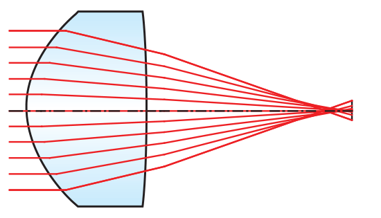
One of the most common types of monochromatic aberrations is spherical aberration. Spherical aberration is the result of light focusing at different locations based on its radial distance from the lens center resulting in poor system performance (Figure 1). Though spherical aberration is present in all spherical optics, an innovative way to correct for it is by employing spherical aberration compensation plates to reduce or remove known quantities of spherical aberration in a system.
WHAT ARE SPHERICAL ABERRATION COMPENSATION PLATES?
By compensating and correcting for a known amount of spherical aberration, spherical aberration compensation plates are single-element optical components that can be easily inserted into a system, reducing spot size and drastically improving image quality (Figures 2a – 2b). These corrector plates signify a change in the way aberration correction can be handled. By correcting for known amounts of spherical aberration, they save in design time, reduction of system weight as well as manufacturing costs.
Spherical aberration compensation plates are designed to be used in collimated space near a pupil. They should be used for systems that have small fields of view such as laser systems or applications imaging point-like objects. These corrector plates can be combined to induce the desired amount of compensatory spherical aberration. Negative sign plates create over corrected spherical aberration, while positive plates create under corrected spherical aberration.
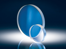
Spherical aberration compensation plates are optically flat windows with low wavefront distortion that have been magnetorheologically polished to impart a mild aspheric surface. Aspheric surfaces are traditionally defined with the following surface profile (sag):
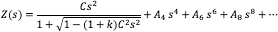
Where Z is the sag of the surface parallel to the optical axis; s is the radial distance from the optical axis; C is the lens curvature, inverse of radius; k is the conic constant; and A4, A6, A8 are 4th, 6th, 8th… order aspheric terms.
However, in the case of spherical aberration compensation plates, there is no optical power (curvature) to the surface (i.e. C = 0). The corrector plates achieve their known amounts of spherical aberration by having at least one non-zero aspheric coefficient. Equation 1 then reduces to:

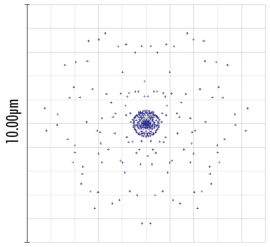
Figure 2a: Spot Diagram of an Optical System with Uncorrected Spherical Aberrations
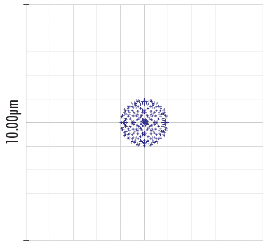
Figure 2b: Spot Diagram of an Optical System with Spherical Aberration Compensation Plate
What are the Benefits of Spherical Aberration Compensation Plates?
Spherical aberration compensation plates represent a shift in the paradigm for how optical designers and industrial end-users compensate and overcome spherical aberrations. They generate a new level of flexibility allowing for aberration correction to take place at the design phase, prototyping phase, or post production phase. Additionally, these corrector plates allow users to passively correct for known amounts of aberrations without a complete system redesign and without the inclusion of software and adaptive optics controls, saving time and money.
Historically, options for correcting spherical aberration have been expensive and cumbersome. These options include the use of adaptive optical systems, liquid lenses, or magnetorheological finishing of the final element in an assembly. In each of these cases, the process for reducing the spherical aberrations can be costly and extremely time intensive; making these solutions not well suited for OEM applications. Fortunay, the implementation of a single spherical aberration compensation plate is two orders of magnitude less expensive than most readily available adaptive optical systems.
Depending on their implementation, spherical aberration compensation plates can be used to improve system performance while reducing the total number of optical elements and thus reducing system weight, assembly time, and cost. As a component-level optic, the applications and benefits of these corrector plates are only limited by the creativity of their end-users.
Spherical aberration compensation plates represent the beginning of a new concept for complete aberration correction. As a result, it now seems possible to solve other aberrations by simply implementing a single optical component into the system level design without requiring a complete system redesign. These corrector plates represent a change in how aberration correction is done and pave the way for additional aberration correction plates (i.e., astigmatism, coma, Petzval, etc.).
How are Spherical Aberration Compensation Plate Innovative?
Optical designers have dealt with trying to compensate for spherical aberrations in their systems for centuries and will continue to do so as improvements in emerging technologies push the limits of optical components. Additionally, optical designers and manufacturers continue to look for designs that reduce aberrations as well as new components that eliminate spherical aberrations all together. With the advent of doublet lenses and aspheric lenses, many optical designers are able to compensate for spherical aberrations within their system during the early stages of design. However, industrial end-users and laboratory researchers often do not have a simple or cost effective solution which easily compensates for these errors.
Current aberration correction methods include the use of adaptive optics: more specifically, deformable mirrors or liquid lenses. The current state of these technologies require the end-user to have an in-depth knowledge of electro-optics and computer programming to successfully integrate a closed loop adaptive optics system. This makes it extremely difficult to quickly and easily improve system performance. Spherical aberration compensation plates represent a truly unique, passive solution for correcting spherical aberrations.
The component nature of the corrector plates drastically increases the product line's lifetime and overall usability. They can be integrated into a system at any point during the production or use-cycles. As a passive optical component, software and electronic advancements do not reduce or restrict the lifetime and usefulness of these products. As long as diverging or converging light is sent through glass (even as a window) spherical aberrations will continue to be a concern for optical designers and industrial end-users. These characteristics make spherical aberration plates a mainstay in the optics industry for years to come.
Real-World Application Examples
To truly understand and appreciate the benefits of incorporating spherical aberration compensation plates into an existing application setup, consider two real-world examples with accompanying equations, illustrations, and Zemax simulations.
Application 1: Spherical Aberration as a Function of Beam Diameter and Wavelength
Spherical aberration compensation plates specify the total amount of spherical aberration imparted on a collimated beam of light covering its entire clear aperture. However, it is often necessary to know the amount of spherical aberration generated by the corrector plate at beam diameters smaller than its clear aperture. If the beam diameter is smaller than the clear aperture, then consider the question, "How much spherical aberration is generated?"
For a collimated beam, the total wavefront error, W(λ,ρ), generated by the corrector plate is a function of both the wavelength and incident beam diameter:
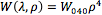
where W(λ,ρ) is the transmitted wavefront error (WFE) due to spherical aberration in units of waves, or λ; ρ is the incident beam diameter divided by the clear aperture of the plate; and W040, which depends on wavelength, is the wavefront aberration coefficient based on the individual plate in units of λ.
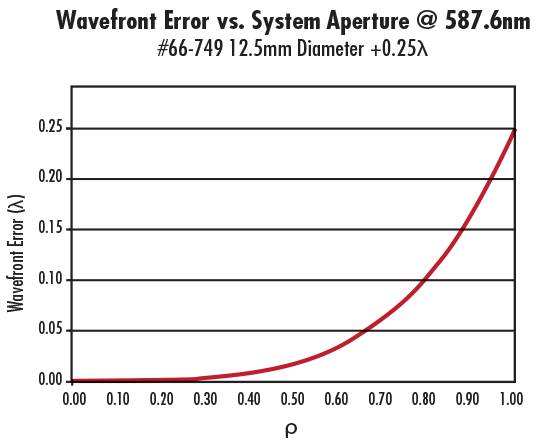
Figure 3: Spherical Aberration vs. Incident Beam Diameter for #66-749 12.5mm Diameter +0.25λ Spherical Aberration Compensation Plate
At 587.6nm, W040 is equal to the wavefront error indicated in the specifications of the individual corrector plate. For instance, for #66-749 12.5mm Diameter +0.25λ plate, W040 equals +0.25 at 587.6nm and the clear aperture (CA) is 11.25mm. It is important to note that Equation 3 is valid only when a collimated beam is incident on the corrector plate; it is not valid if the incident beam is converging or diverging. To illustrate the amount of spherical aberration generated as a function of incident beam diameter, consider #66-749 at 587.6nm (Figure 3).
As mentioned earlier, the amount of spherical aberration generated by the spherical aberration compensation plate is also affected by the wavelength of the light source. Figure 4 shows that #66-749 produces more spherical aberration at shorter wavelengths than at longer ones. Also, this is true regardless of the sign of W040 (Figures 4 – 5). In summary, the magnitude of the spherical aberration introduced by the corrector plate increases with aperture and decreases with wavelength.
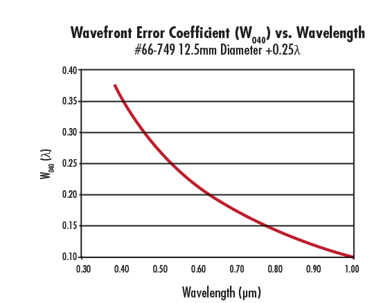
Figure 4: W040 as a Function of Wavelength for #66-749 12.5mm Diameter +0.25λ Spherical Aberration Compensation Plate
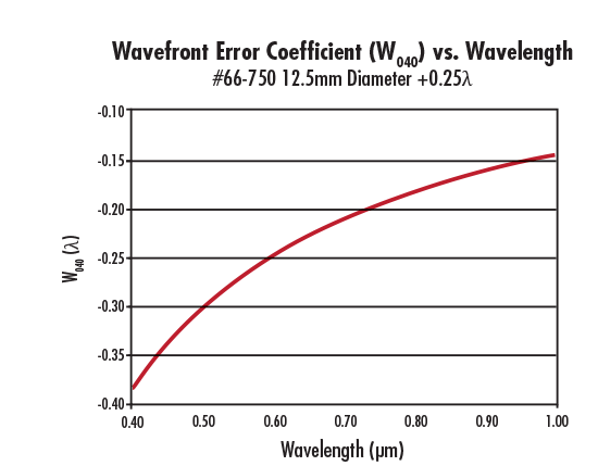
Figure 5: W040 as a Function of Wavelength for #66-750 12.5mm Diameter -0.25λ Spherical Aberration Compensation Plate
Application 2: Correcting Aberration from a Positive Focal Length Optical Lens
A positive focal length optical lens always introduces positive spherical aberration. This is evident from its transmitted wavefront error (WFE) profile and optical path difference (OPD) graph (Figure 6). To correct the positive lens' induced spherical aberration, use a negative spherical aberration compensation plate.
Consider the specific example of using #66-760 25mm Diameter -1.00λ Spherical Aberration Compensation Plate with #32-891 25mm Diameter 200m EFL Plano-Convex (PCX) Lens operating at f/8.89. Figure 6 illustrates the WFE profile and OPD graph of the PCX lens alone, whereas Figure 7 the corrector plate placed on the collimated side of the lens. Without the plate, the PCX lens produces +0.9162λ of spherical aberration; however, with the plate, the resulting transmitted WFE is +0.9162λ – 1λ ≈ -0.0836λ —less than λ/10! Though the numerical difference may be small, the optical difference is significant to anyone trying to correct for spherical aberration.
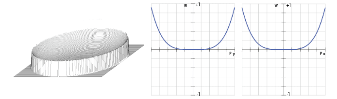
Figure 6: WFE (Left) and OPD at ƒ/8.89 (Right) for #32-891 25mm Diameter 200mm EFL Plano-Convex Lens
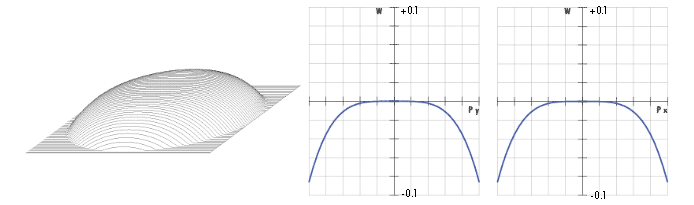
Figure 7: WFE (Left) and OPD at ƒ/8.89 (Right) for #32-891 25mm Diameter 200mm EFL Plano-Convex Lens with #66-760 25mm Diameter -1.00λ Spherical Aberration Compensation Plate
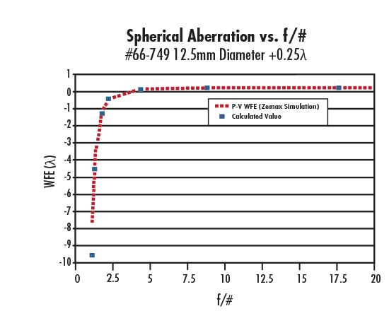
Figure 8: Wavefront Error (WFE) Generated by #66-749 12.5mm Diameter +0.25λ Spherical Aberration Compensation Plate vs. f/#
It is important to note that because the spherical aberration compensation plate was placed in collimated space, the transmitted WFE is independent of the orientation of the aspheric surface on the plate. If the plate is added on the side of the lens where light is converging, then the amount of spherical aberration added by the plate is equal to the amount of spherical aberration produced by a plane parallel plate of the same thickness as the corrector plate plus the amount added if it were used in collimated space. To further understand this concept, consider the amount of induced spherical aberration for a plate placed in a convergent/divergent wavefront:

where W(λ, ρ, t, n, f/#) is the transmitted WFE due to spherical aberration in units of waves, or λ; ρ is the incident beam diameter divided by the clear aperture of the plate; W040, which depends on wavelength, is the wavefront aberration coefficient based on the individual plate in units of λ; t is the thickness of the plate; n is the index of refraction of the plate at wavelength λ; and f/# is the f-number of the convergent/divergent beam.
For an f/# ≥ 10, the wavefront error approaches +0.25 at 587.6nm when using #66-749 12.5mm Diameter 0.25λ Spherical Aberration Compensation Plate (Figure 8).
Optical aberrations exist in all optical, imaging, and photonics systems. The key to achieving the best systems is to understand and correct for these aberrations with the best methods and components. Spherical aberration compensation plates are one of the tools with which optical designers can save in design time, reduction of system weight and manufacturing costs. Spherical aberration compensation plates correct for known amounts of spherical aberration within a system, thereby allowing the implementation a single optical component without requiring a complete system redesign.
版權(quán)所有 © 2025 江陰韻翔光電技術(shù)有限公司 備案號:蘇ICP備16003332號-1 技術(shù)支持:化工儀器網(wǎng) 管理登陸 GoogleSitemap


